🎉 Up to 70% Off Selected ItemsShop Sale
HomeStore

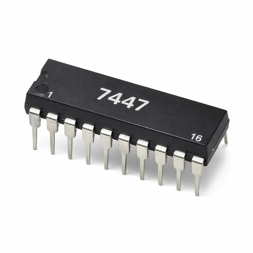
74HC47 ( BCD to 7-Segment Decoder)

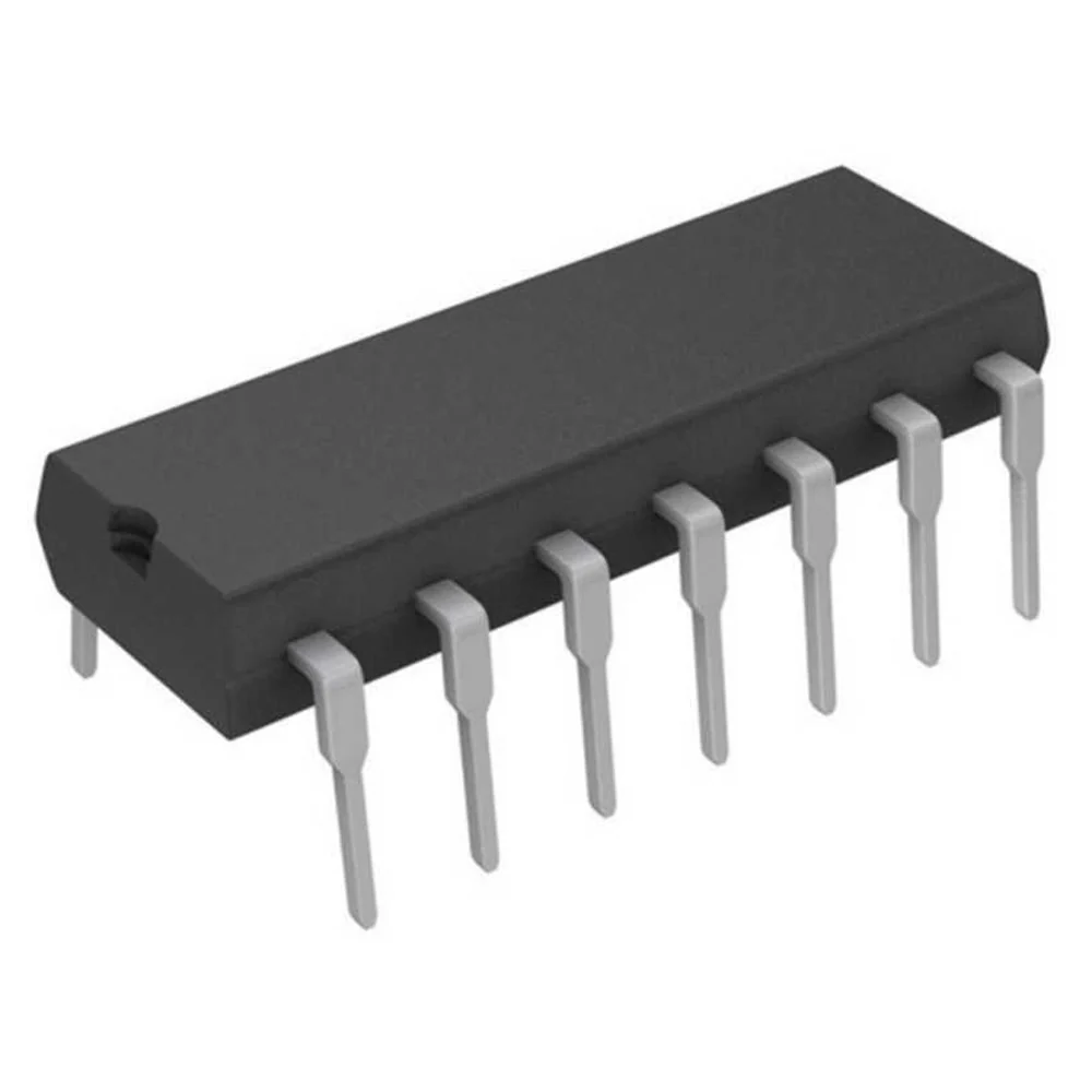
Product image 1

74HC47 ( BCD to 7-Segment Decoder)

74HC47 ( BCD to 7-Segment Decoder)

74HC47 (BCD to 7-Segment Decoder/Driver)

General Description
The 74HC47 is a BCD to 7-segment decoder/driver IC designed to convert a 4-bit Binary Coded Decimal (BCD) input into the correct output signals for driving a 7-segment display. It is commonly used in digital clocks, counters, panel meters, and numeric display circuits.

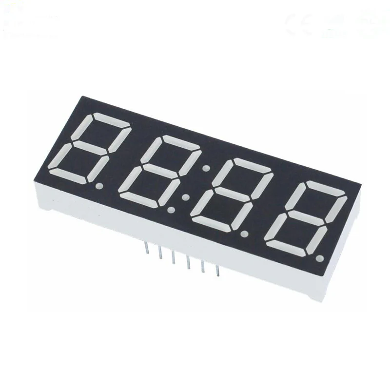
This IC is typically used with common-anode 7-segment displays.

Key Features

  • Converts 4-bit BCD input to 7-segment display output

  • Designed for common-anode displays

  • High-speed CMOS logic

  • Low power consumption

  • Suitable for digital display and counting applications

  • Includes control pins for lamp test, blanking, and ripple blanking

Main Functions

  • Accepts BCD inputs: A, B, C, D

  • Decodes numbers 0 to 9

  • Activates the required segment outputs: a, b, c, d, e, f, g

  • Helps reduce wiring complexity in numeric display circuits

Applications

  • Digital counters

  • Frequency meters

  • Calculator displays

  • Embedded electronics projects

  • Numeric indicator circuits

  • Industrial control panels

Important Note

  • Best suited for common-anode 7-segment displays

  • For proper operation, current-limiting resistors should be used with the display segments

Package Type

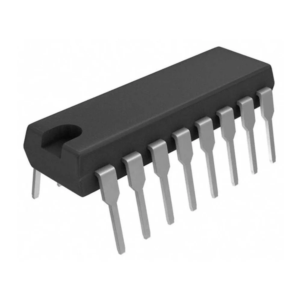
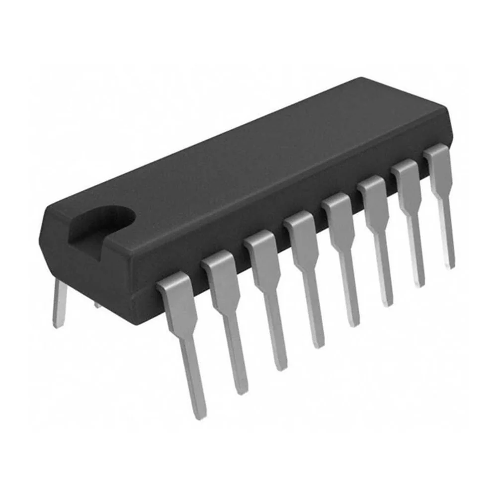
  • Commonly available in DIP-16

74HC47 – Pin Functions 

🧠 BCD Inputs

  • Pin 7 – A: Least Significant Bit (LSB) input

  • Pin 1 – B: BCD input

  • Pin 2 – C: BCD input

  • Pin 6 – D: Most Significant Bit (MSB) input


   7-Segment Outputs (Active LOW – for Common Anode)

  • Pin 13 – a: Segment A output

  • Pin 12 – b: Segment B output

  • Pin 11 – c: Segment C output

  • Pin 10 – d: Segment D output

  • Pin 9 – e: Segment E output

  • Pin 15 – f: Segment F output

  • Pin 14 – g: Segment G output


  Control Pins

  • Pin 3 – LT (Lamp Test): Forces all segments ON when LOW

  • Pin 4 – BI (Blanking Input): Turns OFF all segments when LOW

  • Pin 5 – RBI (Ripple Blanking Input): Used for leading zero suppression


Power Pins
  • Pin 16 – VCC: +5V Supply

  • Pin 8 – GND: Ground

$0.66
74HC47 ( BCD to 7-Segment Decoder)
$0.66

Product Information

Shipping & Returns

Description

74HC47 (BCD to 7-Segment Decoder/Driver)

General Description
The 74HC47 is a BCD to 7-segment decoder/driver IC designed to convert a 4-bit Binary Coded Decimal (BCD) input into the correct output signals for driving a 7-segment display. It is commonly used in digital clocks, counters, panel meters, and numeric display circuits.

This IC is typically used with common-anode 7-segment displays.

Key Features

  • Converts 4-bit BCD input to 7-segment display output

  • Designed for common-anode displays

  • High-speed CMOS logic

  • Low power consumption

  • Suitable for digital display and counting applications

  • Includes control pins for lamp test, blanking, and ripple blanking

Main Functions

  • Accepts BCD inputs: A, B, C, D

  • Decodes numbers 0 to 9

  • Activates the required segment outputs: a, b, c, d, e, f, g

  • Helps reduce wiring complexity in numeric display circuits

Applications

  • Digital counters

  • Frequency meters

  • Calculator displays

  • Embedded electronics projects

  • Numeric indicator circuits

  • Industrial control panels

Important Note

  • Best suited for common-anode 7-segment displays

  • For proper operation, current-limiting resistors should be used with the display segments

Package Type

  • Commonly available in DIP-16

74HC47 – Pin Functions 

🧠 BCD Inputs

  • Pin 7 – A: Least Significant Bit (LSB) input

  • Pin 1 – B: BCD input

  • Pin 2 – C: BCD input

  • Pin 6 – D: Most Significant Bit (MSB) input


   7-Segment Outputs (Active LOW – for Common Anode)

  • Pin 13 – a: Segment A output

  • Pin 12 – b: Segment B output

  • Pin 11 – c: Segment C output

  • Pin 10 – d: Segment D output

  • Pin 9 – e: Segment E output

  • Pin 15 – f: Segment F output

  • Pin 14 – g: Segment G output


  Control Pins

  • Pin 3 – LT (Lamp Test): Forces all segments ON when LOW

  • Pin 4 – BI (Blanking Input): Turns OFF all segments when LOW

  • Pin 5 – RBI (Ripple Blanking Input): Used for leading zero suppression


Power Pins
  • Pin 16 – VCC: +5V Supply

  • Pin 8 – GND: Ground